History of Fracture Mechanics#
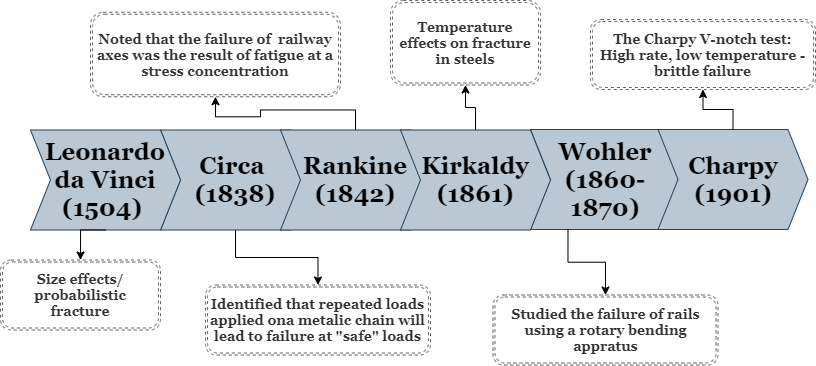
Leonardo da Vinci (1504)#
While testing the strength of Iron wires, Leonardo da Vinci noted that longer wires are weaker than shorter wires (of the same diameter).
Why da Vinci’s results conflicts with the classical theory of mechanics of materials? Can you suggest an explaination as to the why?
W.A.J Albert (1838)#
W.A.J Albert demonstrated that when a mining chain is subjected to repetetive loading it may fail at lower loads than anticipated based on “standard” mechanical tests. This process of unexpected failure was later termed fatigue by Poncelet in 1839
W.J.M Rankine (1842)#
W.J.M Rankine noted that the failure of a railway axel, resulted from a stress concentrator in the form of a sharp angle. It is interesting to note that the first ever commercial jet airliner - Comet has suffered froma similar design issue, rendering Boeing as the dominant commercial use jet airliner of that era.
A. Wöhler (1860-1870)#
A. Wöhler was the first to systematically study the correlation between the number of load cycles to their amplitude, a work which resulted in the well known Wöhler curve or S-N curve. Wöhler’s work revovled mainly around railway axels, whose failure has been a serious cause for concern, leading to multiple accidents.
G. Charpy (1901)#
The famous Charpy test is extensively utilized for both research and design purposes. The combination of a strong stress concentrator, low temperature and high loading rate render this test as highly suitable for material screening and comparison purposes. However, it was not proven yet to have a predictive value.
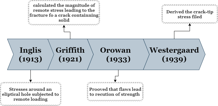
C.E. Inglis (1913)#
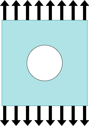
With the aid of linear elasticity, Inglis described the stress in an elastic body containning an eliptical flaw chracterized by \(a,b\) and subjected to a remore load \(\sigma_{\inf}\).
\(\sigma_{ij}\) |
Kirsch’s solution |
|---|---|
\(\sigma_{\theta\theta}\) |
\(\frac{\sigma_{inf}}{2} \left [\left (1+(a/r)^2 \right ) - \left ( 1+3(a/r)^4 \right ) \cos 2\theta\right ] \) |
\(\tau_{r\theta}\) |
\(- \frac{\sigma_{inf}}{2} \left [\left (1+2(a/r)^2 \right ) - 3(a/r)^4 \right ]\sin 2\theta \) |
\(\sigma_{rr}\) |
\(\frac{\sigma_{inf}}{2} \left [\left (1-(a/r)^2 \right ) + \left ( 1-4(a/r)^2+3(a/r)^4 \right ) \cos 2\theta\right ] \) |
|
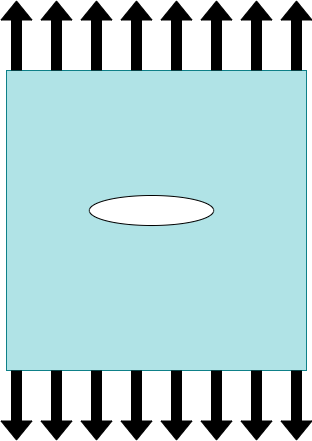
Inglis’s solution is not straight forward to utilize for estimating the stress around the elipse. In fact, prior to the widespread use of computers it was somwewhat limited in its applicability. (Suggested reading: Cook-Gordin toughening mechanism)
The maximum stress arising from Inglis’s solution at the major axis of the elipse is given by:
For the limit of \(a>>b\) :
A.A. Griffith (1913)#
Griffith has introduced the usage of an energy balance to characterise the driving force leading to crack growth. Consider a system (e.g. the plate from above) being subjected to uniform tension, as before. By extending the crack in the plate, the total amount of material able to sustain the load has decrease, such that the strain energy in the plate was modified by :
At the same time, the creation of a new surface has an energetic cost of \(\gamma_s\) per unit area, leading to :
Puttin it all togehther, the total change in the system’s energy is given by:
From here, the stress required to drive crack growth is easily obtainable as:
Note
What are the typical values for \(\gamma\) ? What are the typical values for the energy required to fracture glass? steel? lightweight structural alloys?
E. Orowan (1933)#
In 1933, Orowan have conducted experiments on Mica. Typical reported tensile strength values of Mica were of the order of 200-300 MPa, however, by using a set of grips whose width was smaller than the specimens width, Orowan measured values higher than 3GPa.
H.M. Westergaard (1939)#
Westergaard developed a solution to the stress fields surrunding a crack. His approach consisted of using Airy’s Stress Function \(\phi\) and choosing it to be complex. We will get into more details in {doc}’../LEFM/Crack-tip-fields.md’.
Westergaard’s solution has two advantages over the previously obained Inglis solution:
It is derived directly for a crack and not for an elliptical hole whose limit approaches a crack.
The obtained solution is easier to interpert and apply toward understanding the mechanics of cracks.
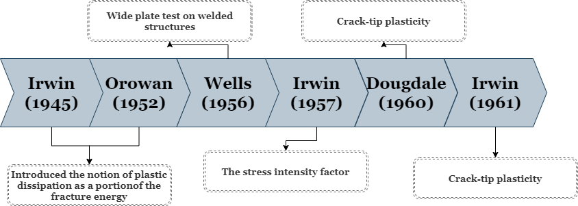
Energy dissipation (Irwin 1945, Orowan 1952)#
In 1913, Griffith suggested that the stress required to fracture a material is proportional to \(\sqrt{\gamma_s}\). Typical values of free surface energy are in the range of 0.1-10 \(J/m^2\), whereas typical fracture energies of structural materials are of the order of \(10^2 - 10^5 J/m^2\). Consider Cu as an example. The surface energy of Cu is reported to be somehwere between \(1.9 - 2.6 J/m^2\) while the fracture energy of pure Cu under quasi-static conditons at RT was reported to be in the range of \(1-2 kJ/m^2\).
Orowan suggest a modification to the Griffith equation such that:
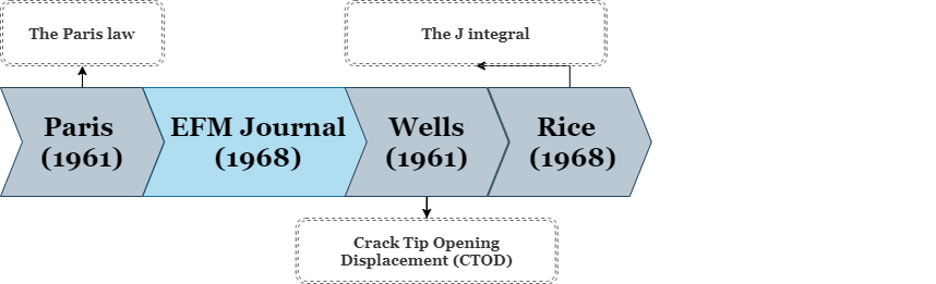
A.A. Wells (1956)#
Welding first enetered industrial use at the end of the 19\(^{th}\) century. Around the time of the second world war, electric arc welding was used for the construction of large steel structures (e.g. the Liberty ships). During that time, the structural steels in use exhibited a Brittle to Ductile Transition (DBT) at ~20\(^o\).
The combined effect of defect formation, heat effected zone and increased DBT led to a large amount of structural failures in the Libertu ships. TheBut it wasnt until 1956, where the first fracture test for a welded plate structure was developed. Wells’ wide plate test consist of a but-welded plate with a cut introduced to the welded region.