The Energy Release Rate#
Let us consider a more generalized case.
We will now try to generalize Griffith’s energy balance by considering a body subjected to load or displacement boundary conditions (or a combination of both).
Similar to Griffith’s energy balance, we will focus on the driving force for crack extension resulting from the re-distribution of energy in the system.
Let us define \(G\) as the amount of energy being released from the system due to an increment in the crack length of magnitude \(\Delta a\) :
Here, \(\Pi\) is the potential energy of the loaded (elastic) body and can be written as :
Let us assume a generalized measure of load ( \(P\) ) and displacement ( \(q\) ).
For the case of load control , \(\delta U\) can be written as:
And for the case of displacement controlled loading we shall obtain the same result:
For a solid elastic body under equilibrium conditions, it is easy to show that
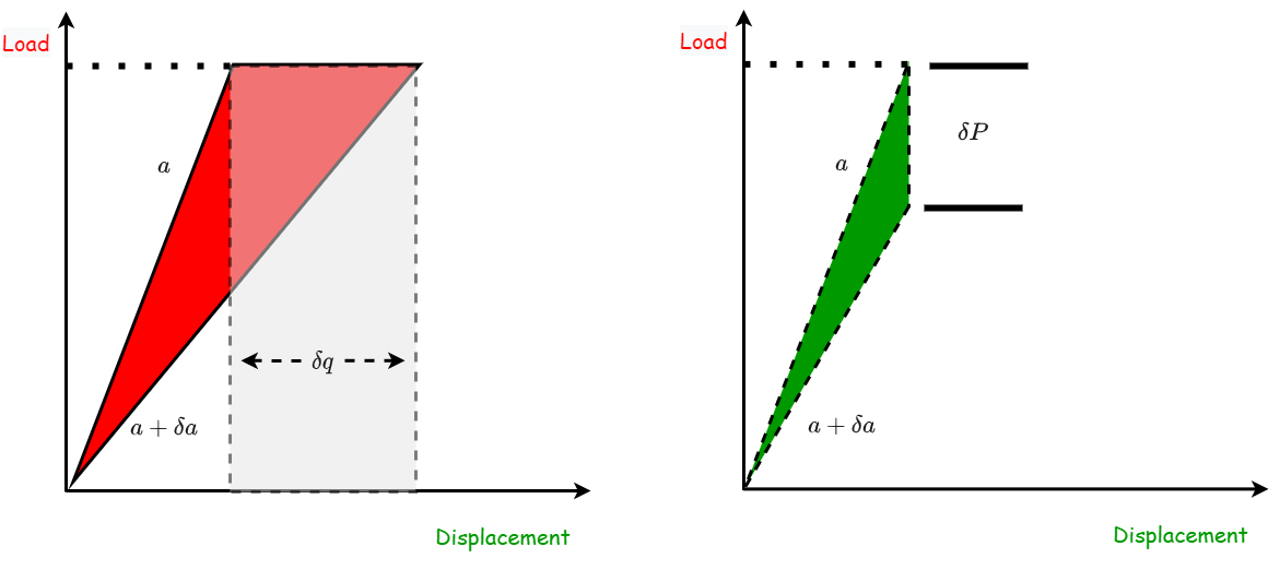
Consider now the bodies in the figure above.
When subjected to predetermined load \(P\) which will lead to a crack extension of \(\delta a\) the change in strain energy can be written as :
Remembering that the applied load is fixed, we can use \(\delta P =0\) leading to:
The expression we obtain ties the change in stored energy to the work done on the system and the work invested in growing the crack by \(\delta a\). rewriting the second term we obtain:
Using
we arrive at :
Now looking at the case where the displacement is prescribed and the load is only measured, we can write:
After the displacement is prescribed and the crack is allowed to grow we have
which in turns, taking use of our definition for \(G\) result in
Note:
The two expressions we obtained for \(G\) are quite different. What are the implications?
Looking at the two expressions in a graphical manner may make it easier to understand:
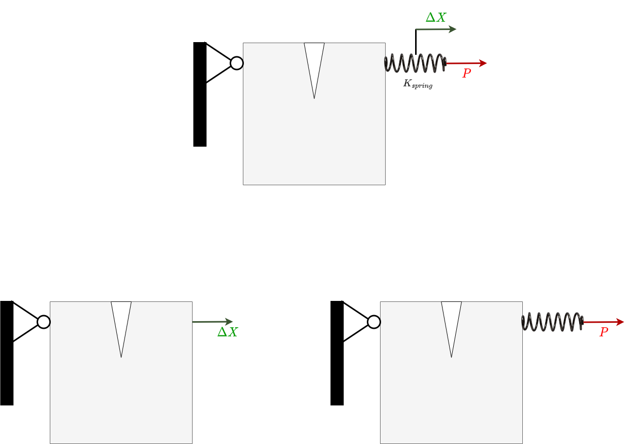
The two extreme cases can be generalized by considering a mixed loading, where the load is applied through a spring.
The overall displacement \(\Delta X\) can be written as :
The derivative of the displacement is \(0\) and \(\Delta X\) can be taken to be a function of \((P,a)\) as can \(G\) resulting in
and using the derivative of \(\Delta X\) we obtain
Crack extension and G#
From the simple analysis above, we saw that for cracks to grow, the system must have sufficient energy to support the crack extension process. In other words, \(G\) needs to obtain a critical value \(G_c\) for cracks to grow in a loaded solid.
Next, we will discuss how to measure \(G_c\). Let us start with a simple example.
Consider a DCB specimen:
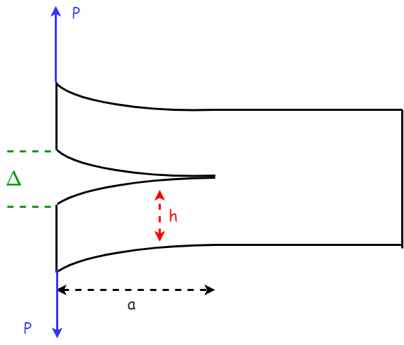
The moment of Inertia for this geometry is known and given by:
With, \(B\) being the DCB thickness. Similarly, using beam theory we can tie the displacement \(\Delta\) to the applied load \(P\) using :
The compliance is thus:
And now we can calculate the driving force for crack extension using (7.1) we obtain:
We can now answer the previous question:
The two expressions we obtained for \(G\) are quite different. What are the implications?
When deriving (7.2) we did not pay any special attention to the way load is applied (i.e. load controlled or displacement controlled).
Starting with the load controlled scenario we can differentiate \(G\) with respect to the crack length. This procedure will help us identify the variation in crack extension driving force as a function of the crack growth.
Next, we will replace P in (7.2) with
So that we can take the derivative of (7.2) with respect to \(a\) under a constant displacement \(\Delta\) leading to :
Looking at (7.3) and (7.4) it is evident that under load control the driving force for crack extension increases with crack growth . On the contrary, for displacement controlled scenarios, the driving force for crack growth has a negative slope and thus decreases as the crack grows . On
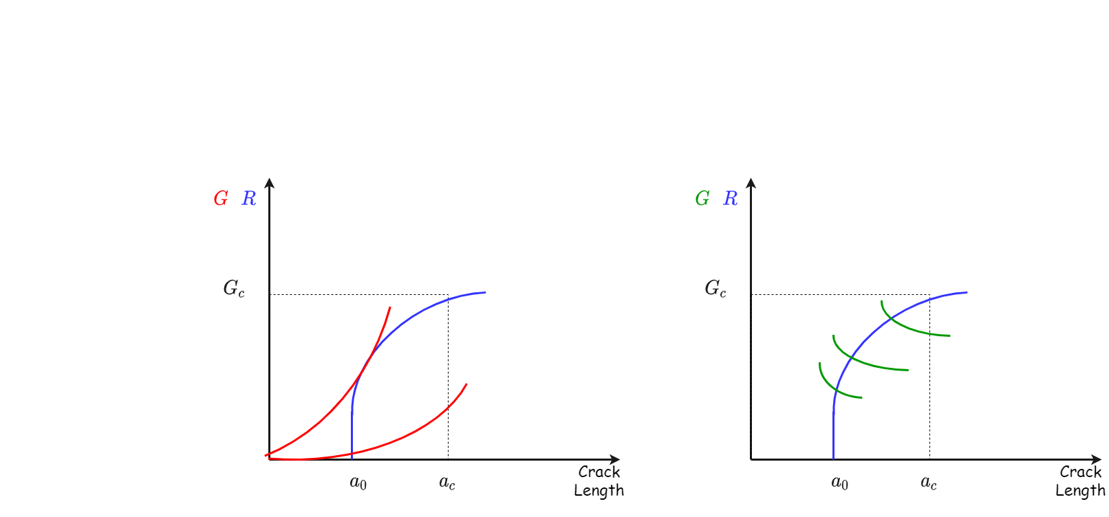
The crack growth resistance curve#
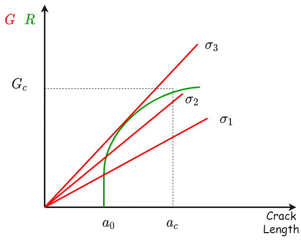
We can write a simple condition for crack growth stability:
As long as as
Crack growth is unstable since the driving force for crack extension increase with the crack growth process itself.
Points for discussion:
What is the meaning of the R curve being flat?
What can cause the R curve to have a positive slope?