3. Paris Law#
In 1963, P. Paris and F. Erdogan published a paper titled A Critical Analysis of Crack PRopagation Laws.
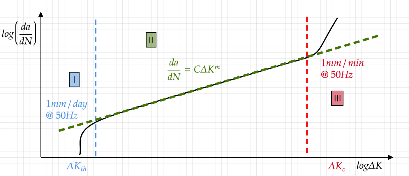
They observed that there exist a region for which the crack propagation with respect to the number of cycles can be written as :
If you think about it, it makes perfect sense. fatigue propagation is the result of the plastic deformation (we will get back to this) at the crack tip, and as such characterizing it using \(K\), when S.S.Y prevail is logical. Moreover, as \(K\) increases it is expected that the crack growth rate will increase.
3.1. Characteristics of the fatigue stages#
Region I
High levels of crack closure
Strong microstructural effects
Enviroment plays a critical role
plasticity is limited in size by the dominant microstructural size (e.g. grain size)
Fracture surface will appear faceted/serrated and originating from the single shear (slip) deformation
Region II
low levels of crack closure
weaker microstructural effects
Enviroment plays a critical role only for certian cases
plasticity is no longer limited in size by the dominant microstructural size
The stress triaxility plays a crucial role
striations appear on the fracture surface
Region III
The stress triaxility plays a crucial role
Strong microstructural effects
Enviroment plays a secondary role
plasticity is larger than the microstructural features
The fracture surface exhibit features such as Dimples/Cleavage
3.2. Loading effects#
When the \(R\) ratio is increased, the crack propagation rate tends to increase as well. Forman proposed to describe this effect using:
which results in an infinite crack growth rate as \(K_{max} \to K_{crit}\)
Various ther forms exist where the Paris equation is modified to account of stress ratio effects, including some designated to allow more freedom in fitting the experimental data and even extending the relation to the \(II\to III\) transition
Another equation, aiming at captruing the effect of \(R\) is the Walker equation,
When assuming that the closure stresses do not contribute to the crack growth, \(\Delta K = K_{max}\).
3.2.1. Crack closure#
At low loads, the compliance of cracked samples can be very close to that of an uncracked body. This suggest that the crack acts is if it is “healed” or “closed”
If we assume that the crack propagation only take place for fully opened cracks we can define \(K_{op}\) as the value for which the compliance returns to that of a cracked body and thus obtain a new effective parameter:
Note, that as the crack extends, the crack closure effects tend to increase up to some threshold with a typical lengthscale as in :
with k being typically of the order of \(1-10^1 mm^-1\).
In Suresh and Ritchie, five mechanisms for crack closure are described :
plasticity induced closure
roughness induced closure
fluid induced closure
Transofrmation induced closire
oxidation (or any corrosion product) induced closure
When the crack is prevented from closing during the application of a compressive load, it leads to a lowe \(\Delta K\) and a higher \(R\).
3.2.2. Retardation and arrest#
When subject to an incidental overload, the plasticity developing at the crack tip (and possibly crack tip blunting) results in a decreased crack growth rate for a number of cycles before regainning the “regular” value.
Wheeler proposed to use a correction function :
with \(R_i\) being the plastic zone size for \(a_i\) crack.
Wilenborg’s model,
Short cracks for cracks sufficiently shorter (compared to the microstructural lengthscale) it was oberved that the crack growth rate can decrease after some propagation regime due to the interaction of the crack with the grain boundary. When the \(SIF\) is low it can even lead to crack arrest.
Often, oscilations in crack growth rate are observed, corresponding to the repeated interaction with GB until the crack is sufficiently long to obey a mechanicaly-short description (\(100\mu -\to 1mm\)).
3.3. LCF crack propagation#
In the low cycle fatigue regime it was shown that the crack propagation rate can be written in a similar manner to paris low:
Tomkins (1968) proposed that the crack growth rate in LCF is proportional to the CTOD
with \(R'_m\) being the ultimate tensile strength. for low enough stress amplitudes this translates to a similar form to (*)
3.4. Life estimation#
Using Paris law we can estimate the life of a component.
Recalling that
\(\Delta K = Y(\theta,a)\Delta \sigma\sqrt{\pi a}\)
we can write
and after integration (\(a: a_0 \to a_f \ \ N:0 \to N_f\)) we obtain
For \(m=2\)
For \(m \ne 2\)
The values of \(a_0\) and \(a_f\) will determine the \(N_f\) for a given material/structure combination.
The determination of these values is typically done through a combination of several factors:
NDT techniques used after manufacturing
NDT techniques used for structural health monitoring and routine inspection
The desired maintance scheduele
Design and safety considerations
crack tolerant design
Can we allow a component with a detected crack to stay in service?