1. Fatigue: Choosing a Design Approach#
Fatigue is the process of damage nucleation and accumulation resulting from repetitive loads.
According to a survey conducted in [2002](Why aircraft fail - ScienceDirect) 55 percent of failures in aircraft components are the result of fatigue, with Corrosion being the second runner up (14%).
If you remember, many of the early investigations into fracture mechanics were conducted to understand the origin of fatigue induced failures.
Indeed, designing for fatigue requires that we take a slightly different approach than simply assuring that the structure is safe under the maximum expected static load.
Following the work of Wohler, we know that as the expected life time of a component extends, smaller loads become dangerous to the structure’s health.
Fatigue is influenced by many factors, including:
The load amplitude and the ratio between the maximum and minimum loads
The mean stress
The loading history
Environmental effects (chemistry, temperature)
The material’s microstructure
Surface properties
Internal defects
Before diving into how those factors influence the reliability of our structures, lets compare two design approaches:
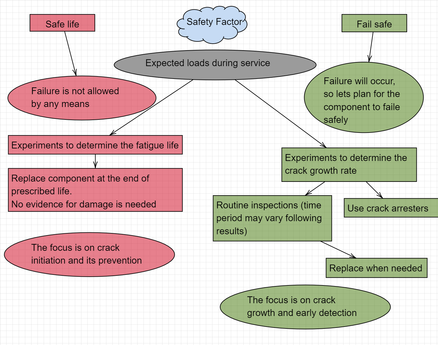
So, which tools and models can we use for each approach ?
1.1. Definitions#
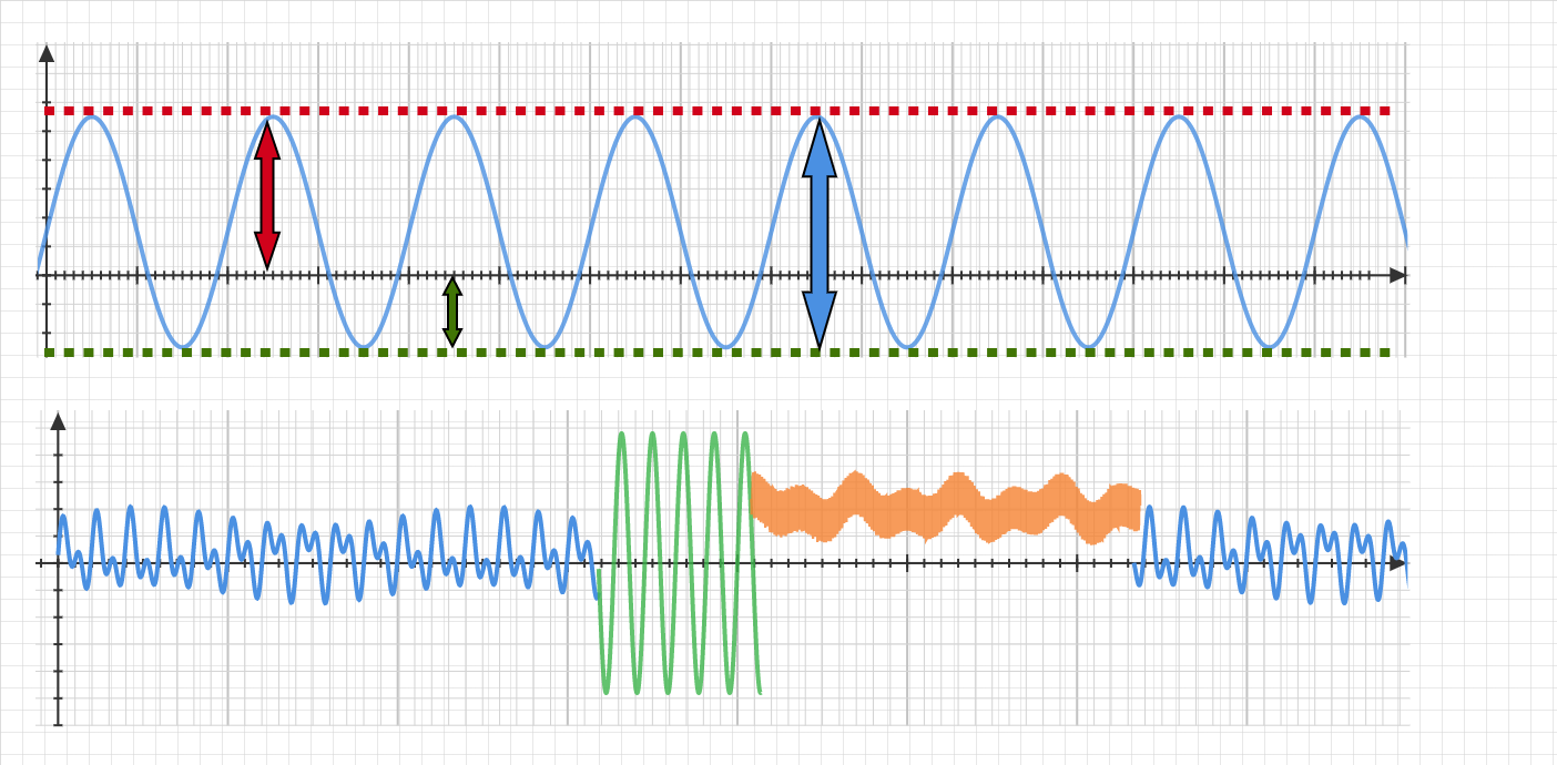
\(\color{red}{\sigma_{max}}\) Maximum applied stress
\(\color{green}{\sigma_{min}}\) Minimum applied stress
\(\color{blue}{\Delta \sigma}\) Stress range
\(\sigma_a = \frac{{\color{red}{\sigma_{max}}}-\color{green}{\sigma_{min}}}{2}\) Stress amplitude
\(\sigma_m = \frac{{\color{red}{\sigma_{max}}}+\color{green}{\sigma_{min}}}{2}\) Mean stress
\(R = \frac{{\color{green}{\sigma_{min}}}}{{\color{red}{\sigma_{max}}}} = \frac{{\color{green}{K{min}}}}{{\color{red}{K{max}}}}\)
\(\color{blue}{\Delta K}\) Stress intensity factor range
1.1.1. HCF high cycle fatigue#
Typically \(N>10^5\).
Low stresses
Fatifue models are based on LEFM and plasticity is negligible
Stress is the main characterizing parameter
1.1.2. LCF low cycle fatigue#
Typically \(10^2<N<10^5\)
Non negligible plasticity \(\left(1<\frac{\Delta \epsilon^p}{\Delta \epsilon^e}<10\right )\)
Fatifue models are based on \(J\) as a fracture parameter (LEFM is not applicable)
Strain is the main characterizing parameter
1.1.3. VLCF very low cycle fatigue#
Typically \(1^2<N<10^2\)
Non negligible plasticity \(\left(10<\frac{\Delta \epsilon^p}{\Delta \epsilon^e}<100\right )\)
Fatifue models are based on \(J\) as a fracture parameter (LEFM is not applicable)
Strain is the main characterizing parameter
1.1.4. Initiation#
While related to loads within the elastic regime fatigue is a plasticity phenomena.
With cyclic strainning, dislocations begin to slip and interact leading to strain hardening due to the increase in \(\rho\).
Near the specimens surface (assume zero roughness for now) deformation is substantially easier. the slip traces observed on the surface leads to crack initiation which propagates at angle (typically 45 degrees) to the applied load. When encountering a grain boundary or similar obsticales, the crack realigns to follow the mode I direction.
Dislocations accumulation at grain boundaries leads to GB cracking
Impurities, particles, second phases etc. located near the sample surface can lead to strain localiztion routes on whic cracks will nucleate.
Defects and surface roughness play an important role in nucleation.
1.1.5. Growth#
Striations are the manifestation of incremental crack growth and can be correlated with the CTOD
When initiated from a strong stress concentrator, cracks will deaccelerate