Strain Measurments
Contents
11. Strain Measurments
See also
This is a good oppurtunity to remind you of the course books as well as another reccomended book focusing on experimentalsolid mechanics.
Strains can be measured by either *contact or non-contact techniques. Choosing the appropriate strain measurement instrumentation is dependent on:
The magnitude of the strain we wish to measure.
The location of the measurment.
The purpuse of the measurement.
The rate/frequency at which the strain varies.
Among the various methods for strain measurement we can find:
Unidirectional displacement sensors (LVDT, Glip-on gauges, optical barcodes etc.)
Those are typically used for measuring an avarage strain value via \(\epsilon = \frac{\Delta L}{L_0}\)Strain gauges (resistance based)
S.G are used for local strain measurements and can provide uni-directional as well as multi-directional (rosette) information. Depnding on the required sensitivity metallic or semiconductor based S.G can be used. Similarly, S.G are available for both quasi-static and transient regimes and different enviromental conditions.Photoelasticity methods
Photoelasticity provides a mean for obtaining a field quantity, i.e. a strain map, based on the relation between the material’s optical properties and the experienced deformation. This method can be used directly on photoelastic materials or in-directly on any other material through the usage of special coating materials.Digital Image Correlation (DIC)
DIC is an optical method used for mapping the displacement field in 2D or 3D. It is a non-local or field method who has found its way into many industrial and academic sectors. An extension of this approach, often reffered to as DVC takes advantage of advance imagng capabilities (\(\mu\)-CT) to probe the deformation fields in a material/structure interior. The camera resolution, image quality (e.g. stigmation, depth of focus, lens abberations etc.) and frame rate are to be considered prior to designing the experiment.Diffraction methods (X-Ray, Neutrons, etc.)
Elastic strain at the bulk results in variations in the diffraction pattern which in turn can be traced back to their origin. Extremely small strains can be measured using such methods at various enviromental conditions and rates.
11.1. Strain Gauges
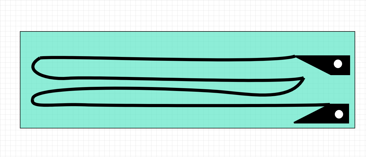
The most common strain gauge is constructed as a thin flexible foil with embeded metallic wires. The spatial arrangement of the wire dictates the measuring direction
As the wires change their length, their resistance is changing following
The axial strain is given \(\to\) \({\color{red}{\frac{dL}{L}}}\)
Poisson effects \(\to\) \({\color{blue}{\frac{dA}{A}}}\)
Piezoresistivity \(\to\) \({\color{green}{\frac{d\rho}{\rho}}}\), for metals the contribution of this term is negligible but for semiconductor based S.G this term becomes dominant and is responsible for their non-linearity.
The parameter controlling the strain gauge sensitivity is called Gauge Factor (GF) :
In metals the GF usually revlves around 2 while in semiconductor based S.G GF~200.
S.G are (mostly) measured using a Wheatstone bridge
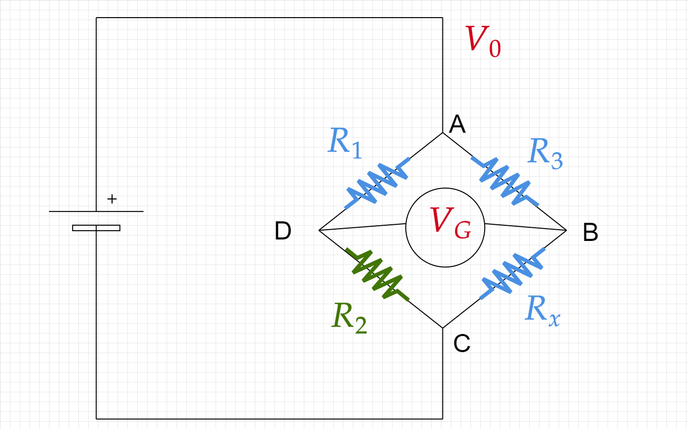
The resistor \(\color{green}{R_2}\) is a varaiable resistor and is used for zeroing the voltage:
The resistance \(R_x\) is monitored through out the deformation and translated into strain.
Which is leads to
11.1.1. Pitfalls and Limitations
S.G requires excelent adherence to the sample. A S.G which was not properly glues or somehow partially detached from the sample will lead to a sensitivity erro.
Restricted to relatively small strains.
Susceptible to thermal effects (external and internal)
The current levels (and hence applied voltage) must be kept low to avoid heating during the measurement.
Unforseen bending/torsion etc. will lead to S.G extension while we assume the deformation to be strictly uni-axial.
11.2. Digital Image Correlation (DIC)
1. [Society of Experimental Mechanicd DIC Challenge](https://sem.org/dicchallenge)
2. [The international DIC Society](https://www.idics.org)
3. [DIC codes and commercial softwares](https://www.idics.org/resources/)
DIC is based on identifying the displacement of features in the image between consecutive frames.
There are many different algorithm used for detecting the displacement, and we will not cover them here.
The majority of DIC codes rely on the user to generate artificial patterns on the surface prior to the experiment. In some cases (and some algorithms) this can be avoided. However unless you have a good reason not to do so it is prefferable to use an artificial speckle.
The GPG issued by iDICs is a good source to start and get the hang of what is important when designing an experiment based on DIC.